Osiris
UAV fabrication and flight testing
I fabricated approximately 99% of Osiris, performed all PID tuning and the majority of flight testing, and integrated its payload. My work also included structural modeling, component specification, and battery packaging and retention. The completed Poly UAS aircraft placed third overall in competition.
Competition aircraft · 2025–2026
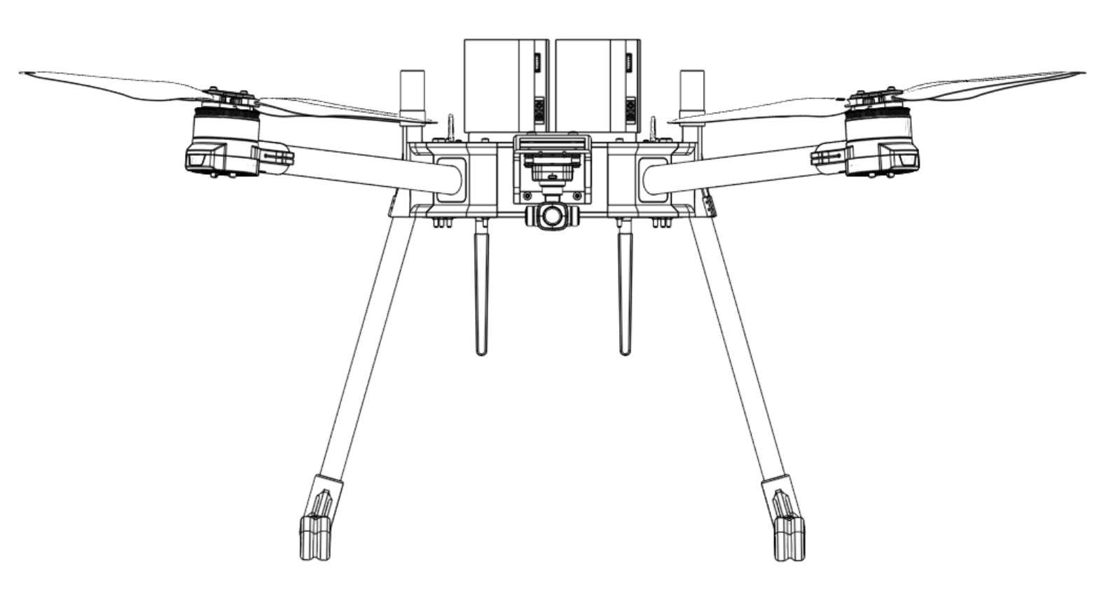
The team aircraft lifted the heaviest package and achieved the most accurate package placement. Fabrication, tuning, testing, and payload integration were my principal areas of work.
01 / Aircraft architecture
A complete heavy-lift quadcopter
Four carbon-fiber arms carry the propulsion assemblies around a central structure. The completed aircraft packages power and flight hardware above an underslung payload frame, with landing gear providing ground clearance around the payload.
Structure and packaging
I modeled structural components in Onshape and specified individual components against the aircraft architecture. Arm attachments, central packaging, and payload access connect the mechanical layout to subsystem requirements.
Flight hardware
Propulsion, power, flight control, and navigation hardware had to function as one aircraft. My fabrication and commissioning work carried the design into an assembled, flight-tested vehicle.
Payload position
The installed frame hangs beneath the center section, between the landing legs. This location makes attachment access, ground clearance, and the relationship between suspended mass and aircraft balance important integration considerations.
02 / Fabrication & assembly
From CAD to competition hardware
I personally fabricated approximately 99% of the physical aircraft and carried out its mechanical assembly. That work brought printed parts, carbon-fiber members, mounting hardware, and subsystem packaging together into the completed vehicle shown below.
- Structural components
- Fabrication and fit-up of the aircraft’s mechanical assemblies, connecting the CAD geometry to the manufactured parts and surrounding hardware.
- Mechanical integration
- Assembly of the central structure, arm and propulsion interfaces, landing structure, and payload attachment arrangement.
- Commissioning
- Transition from the assembled aircraft to flight-control tuning and flight testing, followed by payload integration and competition preparation.
03 / Flight control & PID tuning
Commissioning the aircraft’s flight response
I performed all PID tuning and the majority of Osiris’s flight testing. This work connected the physical aircraft configuration to its flight-control response and supported preparation for the payload task.
Attitude and rate control
In a multirotor controller, an attitude command leads to a desired angular rate; the rate controller then adjusts the motor outputs. PID gains influence how the aircraft follows those commands and responds to disturbances.
My responsibility was tuning Osiris’s controller on the real aircraft, using flight testing to assess the response as the system was commissioned.
- PID tuning
- All tuning performed by me. Tuning was part of commissioning and flight-test refinement.
- Flight testing
- I conducted the majority of flights used for commissioning, tuning, and preparation of the aircraft.
- Demonstrated outcome
- A completed, flown aircraft that participated in the 2026 competition. Competition results remain credited to the full team.
04 / Payload integration
Underslung payload frame and winch assembly
I integrated the payload into the aircraft. The supplied Mainassembly CAD view contains the payload subassembly labeled Assembly 9: a braced housing around a spool, shaft, bearing supports, and servo hardware. The upper surface carries two parallel mounting rails.
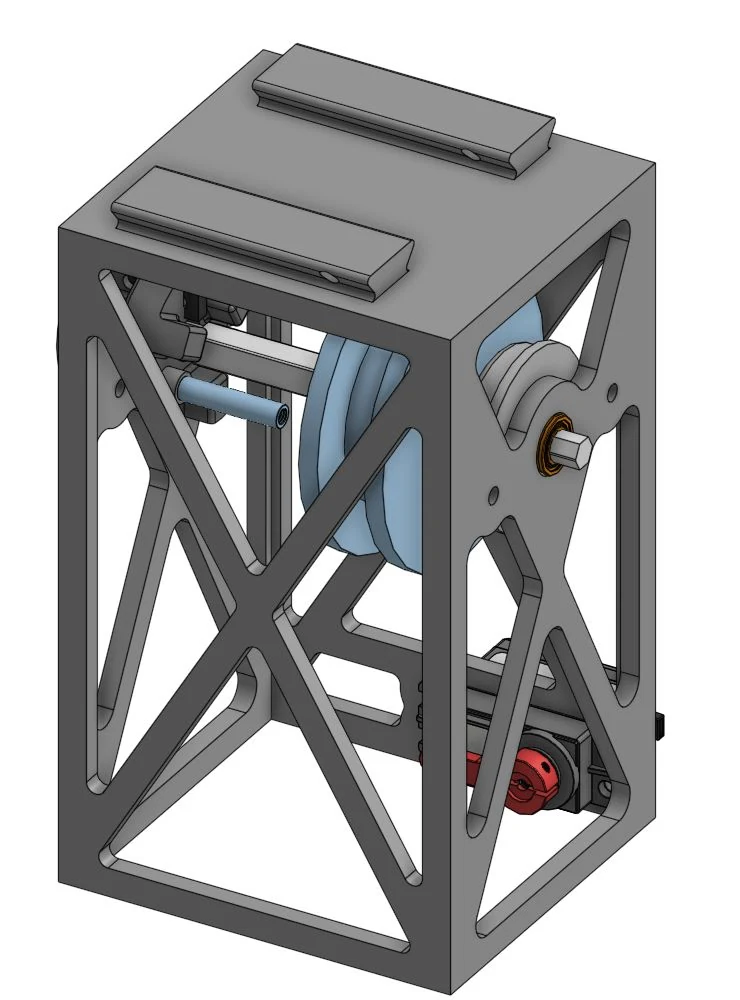
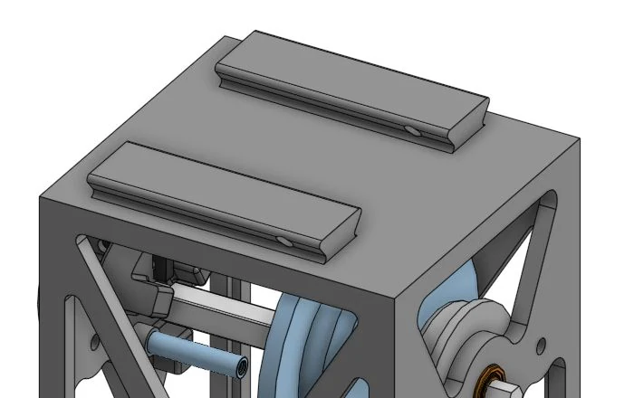
Mounting interface
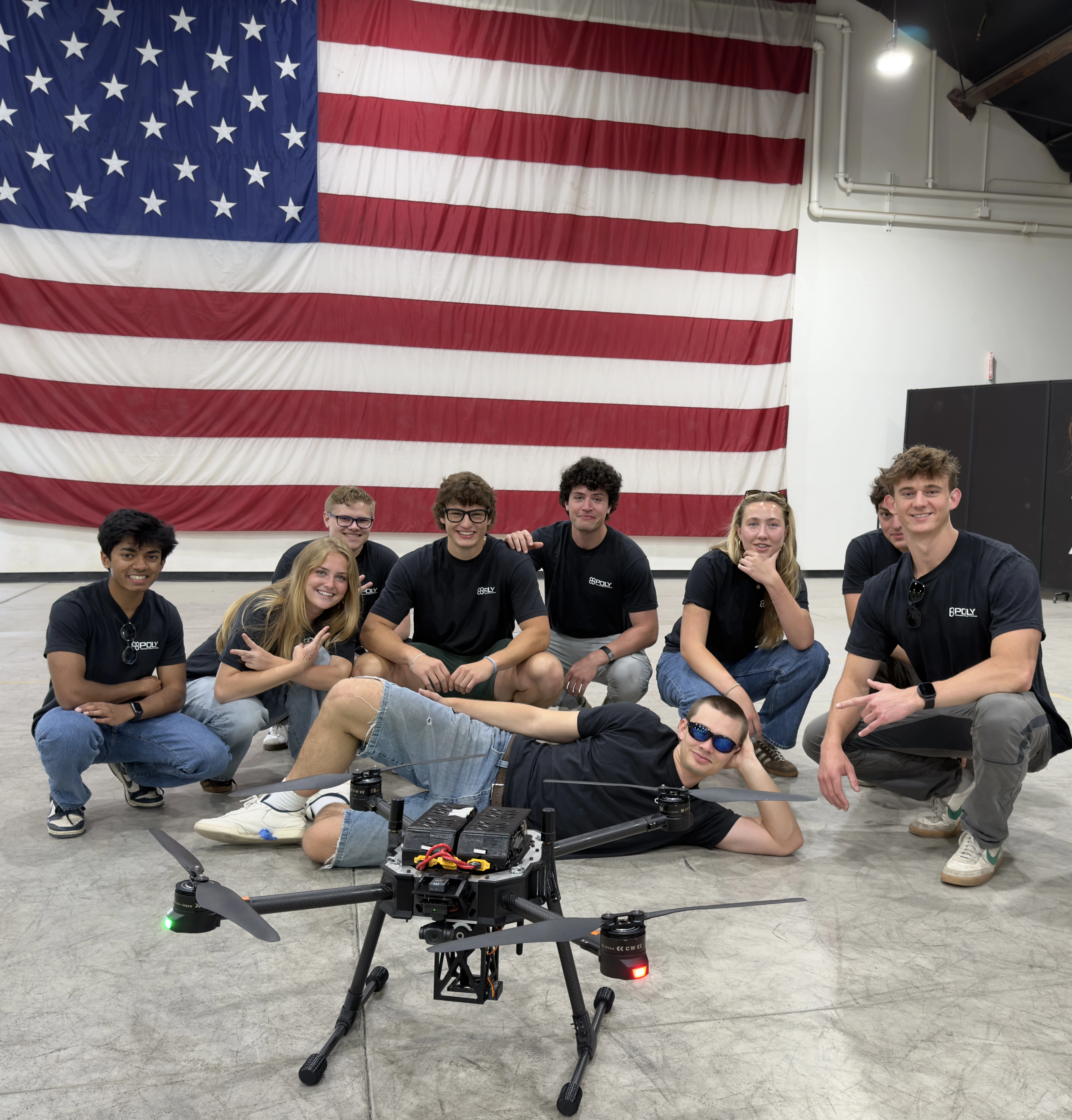
Two raised rails sit on the top plate. The plate connects these attachment features to the surrounding braced frame; the competition photograph shows the payload installed beneath the aircraft.
Spool and shaft support
The spool is arranged on a transverse shaft supported at the housing sides. The model tree identifies the Shaft, Spool, and two Ball Bearings 8mm rex instances, making the rotating assembly and its support interfaces explicit.
Actuation and access
The assembly includes servo hardware, a rack, lock, and a component labeled viscous damper. Large side openings expose the internal mechanism and fasteners. These views document the modeled arrangement, rather than a measured lifting capacity.
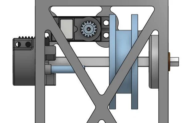
Front assembly view and integration constraints
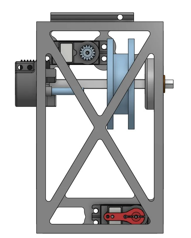
Integration required accommodating the frame below the center structure while preserving landing clearance and access to the attachment and moving parts. Payload mass and position affect aircraft balance; clearance and control response therefore belong to the aircraft-level integration work, not just the standalone mechanism.
The supplied workspace is currently displayed as a payload-only configuration. The competition photograph provides the installed-aircraft context; mating fasteners, payload mass, and electrical pin assignments are not specified by these views.
05 / Power packaging
Shared battery architecture and retention
I worked on the 21700-cell 6S4P packaging and compliant retention design used for Osiris. The same pack architecture is used in Munnin; it is not a separate Osiris-only battery design.
Cell arrangement
Six series groups with four cells in parallel give a 24-cell pack. Packaging the cell envelope and its enclosure is a mechanical integration task alongside the aircraft’s power requirements.
Mechanical retention
The compliant latch combines pack retention with an accessible release, addressing security in the aircraft and access during replacement.
Design progression
The shared pack’s updated enclosure and retention CAD are documented on the Munnin power-system section.
06 / Competition & flight testing
The completed aircraft and team
Osiris completed the build, commissioning, tuning, and flight-test work needed to reach competition. I conducted the majority of flight testing and integrated the payload; the third-place result reflects the work of the full Cal Poly PolyUAS team.
Completed hardware
The photograph shows the physical structure, propulsion assemblies, top-mounted power hardware, and the payload installed below the center section.
Installed payload
The lower payload frame sits between the landing legs. This photograph complements the isolated CAD views by showing the real aircraft configuration.
Competition outcome
The team placed third overall, lifting the heaviest package and achieving the most accurate package placement.